
#particle #photon #guitar #pedal #LTSpice #subcircuit #layout #preroute #PCB
Fig. 1: Completed PCB Layout of Photon Guitar Pedal.
Design Description
The Photon Guitar Pedal is designed to amplify, process, and capture a raw instrument signal, e.g. the signal from an electric guitar pickup, with the Analog-to-Digital Converter (ADC) of a Photon board. Guitar effects pedals are used to enhance the raw signal coming from a guitar by improving aspects such as tone, dynamic range, and equalization, or adding desirable effects such as harmonics, delay, or distortion. This pedal includes both a compression and distortion effect.
The compression signal path utilizes a variable gain amplifier to increase the dynamic range of recording by amplifying softer signals more and louder signals less. This allows us to use a higher gain on our input while still avoiding clipping which produces unwanted noise and distortion. This process is often performed by a standalone Compression Effects pedal such as the MXR DynaComp. The distortion signal path utilizes a high-gain amplifier to force a smooth clipping (that is now intended) and give our signal that classic sound electric guitar sound. This circuit can also function as another clean amplifier if the gain is dialed down. This distortion process is often performed by a standalone Distortion Effects Pedal such as the Fulltone OCD.

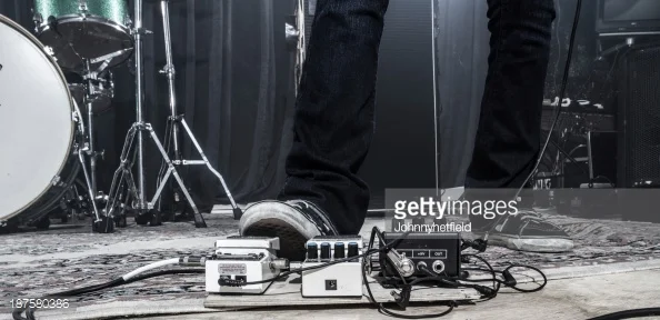
Fig 2: Two examples of guitar pedals similar to those designed in this project.

Photon Guitar Pedal v2.1 Product Features
- 1/4" Input jack with adjustable gain.
- 1/4" Output jack with adjustable attenuation.
- On-board Compression Effect with "Active" indicator LED.
- On-board Distortion Effect with adjustable gain.
- Effect selector switch with Bypass option.
- "Power-on" LED.
Design Overview
I designed this pedal by assembling a number of different subcircuits and components in the Photon Shield Template. Most of the individual subcircuits that are used in this design were made from scratch, but they have all been uploaded to the subcircuits server and can be reused in any design. In the PCB Design section, I discuss the process of developing a subcircuit and creating a preroute for it using the MetaMorph Tools. Also, to understand the benefits of using the MetaMorph Web Tools, check out the rebuild of this design.
Fig. 3: Photon Guitar Pedal Overview Diagram
The Initial Design
As project developed I added more features, but I began the design process with the only simple goal of building a compressor that would accept a guitar signal. A little bit of research uncovered that a guitar signal from an electric guitar or an acoustic-electric pickup is usually on the order of 0.1V and has an output impedance on the order of 1MΩ. (This high output impedance is why if you just plug headphones into your electric guitar, your won't hear anything. The high output impedance can't drive the extremely low input impedance of the headphones.) In addition to accepting a guitar signal, I wanted the output of the compressor to be around 3V peak-to-peak given the 0-3.3V scale of the Analog to Digital Converter on the photon board. A larger signal means a more accurate reading from the ADC, which means a higher quality recording.
COMPRESSOR DESIGN
I searched the internet for a few different compression circuit diagrams and settled upon the compressor circuit that is described by this review: Rockman Guitar Compressor. I reconstructed this circuit in LTspice to find the right values to accomplish the desired compression given a 200mV peak-to-peak amplitude of a raw instrument signal. LTspice is a free tool provided by Linear Technology that allows a user to perform a transient analysis of a circuit over a certain period of time. We can use a transient analysis to see how our circuit will respond to a specified input. For my initial testing, I used three separate voltage sources to model an arpeggiated C chord.
When I started selecting components I chose to the OPA344 operational amplifier (op-amp) for this circuit since it works well with a 3.3V input and I knew I could get the spice model from the MetaMorph component library. Here's how I copied over the OPA344 Spice model for use in LTspice:
- Find the OPA344 component on the MetaMorph Component Browser.
- Download the component and extract the files.
- Copy and paste the "Spice/OPA2344.cir" file to the same directory of your LTspice model.
- In LTspice click Edit > SPICE Directive.
- Type ".lib OPA2344.cir" in the dialog.
- Click OK and place the directive on your canvas.
- Click Edit > Component.
- Select or type "opamp2".
- Click OK and place the component on your canvas.
- Right-click the component, replace the value "opamp2" with "OPA2344", and click OK.
Design Challenge: One of the difficulties of designing this circuit was the tight 3.3V difference in the V+ and V- inputs of the op amp, also known as the rail-to-rail voltage. Most audio equipment uses rail-to-rail voltages varying between 9-30V. This low-voltage range requirement meant that the circuit didn't have very much headroom and I had to find an N-channel FET that would turn on with only about 1V across the Gate and Source. I ended up using the 2N4338. For this same reason, I also had to find a diode that have a very low forward turn-on voltage, and the MMSD4148 turns on with only about 0.3V. Check out General Guitar Gadgets for more information on guitar pedal design!
Fig. 4: The Photon Guitar Compressor project modeled in LTSpice.
After I verified a reasonable working design, I constructed the whole project in GME to allow for further, more-accurate testing and verification and the ability to easily design and manufacture a PCB. (The process of laying out the PCB is described in detail below in the PCB Layout with MetaMorph Desktop Tools section.) Here is a look at the finished PCB design:
Fig. 5: The Photon Guitar Compressor PCB, my first version of the Photon Guitar Pedal project.
The Revised Design
When I brought my design proposal to my team, they liked where the design was going but wanted to add a couple of features: a distortion effects circuit in addition to the compressor circuit that would produce a more noticeable effect on the sound and an output jack so the effects could be more readily observed. I decided to also include an input preamplifier and an output attenuator that would allow for level adjustment before and after the effects circuits.
Distortion Effect DESIGN
I searched the internet for a few different simple distortion pedal circuits and ended up building a modified version of the MXR Distortion Plus replica design on the General Guitar Gadgets website. This circuit is simply a high-gain amplifier with clipping from two diodes at the output. My design utilizes two diodes instead of one to allow for a greater swing in the output before clipping so this circuit could double as a general purpose amplifier.
INPUT PREAMPLIFIER and Output Attenuator
For the input preamplifier, I used a non-inverting op-amp gain circuit to allow for the high input impedance that is needed. The finished preamplifier has a gain (output level divided by input level) that ranges from 0.32 to 3.49 with a simulated 1Meg output impedance guitar signal. As for the output attenuator, I wanted to give the user the ability to put the signal back in a signal chain so I coupled the output signal to ground with a 4.7uF electrolytic capacitor and provided a voltage divider that allows the output to be attenuated from 520mV peak-to-peak down to 0mV peak-to-peak.
The Final Design
The last time I brought the design to my team, they only suggest minor improvements including: an "Active" LED to the compressor circuit to indicate high compression, a "Power-On" LED, local bypass capacitors for each of the op-amps, and a silk screen that would indicate the proper orientation of the Photon on the shield.
I completed these minor changes in both LTspice and GME and plotted the two different effects in LTspice again to verify that they still functioned as expected.
Fig. 6: Final design of the Photon Guitar Pedal in LTspice.
Figure 7 shows an analysis of the compressor. The green trace is the output of the compressor. The blue trace is the input signal normalized to the maximum gain of the compressor. As you can see the compressor cuts the amplitude almost in half at the higher input levels. The red trace is the output of the LED which stays high throughout the time the chord is being played and returns low after the gain comes within about 5% of the maximum gain.
Fig. 7: Compressor Analysis. The output of the compressor circuit in green is overlaid on an input signal normalized to the circuit's uncompressed gain in blue. The red shows when the LED is on that indicates the compressor Is active.
Figure 8 shows an analysis of the full signal chain. It starts with the raw guitar signal in blue, and continues with the input to the preamplifier in green, the output of the preamplifier in red, the output to the distortion effect in teal, and the attenuated output at the output jack in magenta.
Fig. 8: Here you can see the complete signal chain from the Guitar Source > Input > Preamplified Signal > High-Gain Amplifier > Attenuated Output. You can see the distortion and hard clipping of our over-driven high-gain amplifier.
Finally, as you can see in Figure 9, the top-level model is the MetaMorph Desktop Tools looks strikingly similar to the conceptual diagram of the product in Figure 3. The ability to encapsulate certain sections of the design in conceptual blocks is one of the great benefits of designing with the MetaMorph Tools. Next, I'll show you how the tools were used design the PCB board throughout the process.
Fig. 7: The final Photon Guitar Pedal design in the MetaMorph Desktop Tools.
PCB Design with MetaMorph Desktop Tools
As I mentioned above I modeled the project in the MetaMorph Desktop Tools throughout the whole design process. If you haven't used the Desktop Tools before, I would encourage you to visit the LED Tutorial for a basic introduction to the tools and concepts. To aid in the layout design of the final PCB, I chose to pre-route each of the subcircuits individually and then compose them together to yield the final project PCB. At each stage of the design process, I updated the MetaMorph model with the changes that I made in LTspice and regenerated subcircuit preroutes and a new final board.
Fig. 10: The Audio Distortor subcircuit schematic in the MetaMorph Desktop Tools.
For each of the subcircuits like the one pictured above in Figure 10, I would generate a preroute using the following method:
- Run a "PlaceAndRoute" Test Bench on the the subcircuit using a liberal estimate of the size of board space necessary. (For each of these subcircuits I started with a 15mm height and width, but you can just keep running the test bench with a larger and larger board until one places correctly.)
- Open the Eagle board file "schema.brd" that is produced in the results folder.
- Rip up all the routes.
- Rearrange the components in a logical fashion, placing rotary potentiometers and other big components first and ensuring that bypass capacitors were place close to the ICs they were decoupling.
- Run the auto-router to see if there is a viable routing given the placement.
- Repeat steps 3-5 until there is a working route.
- Save the finished board file, close both the MetaMorph Desktop Tools and the Eagle, and use the LayoutReimport.bat file to save that preroute layout in the MetaMorph project.
Fig. 11: Here is the completed preroute of the Distortion Subcircuit in Eagle.
After each of the subcircuits was prerouted, I ran a PlaceAndRoute Test Bench on the Photon Guitar Pedal itself to begin a final layout for the project. Again I chose an extra large board size (100mm height and width) and then shrunk that down as I began to place components and find what would be a reasonable final size. The board ended up being 59mm by 52mm.
Fig. 12: Final layout with subcircuits and other components placed around the Photon Board interface headers.
Note: The six circles that you see on the board that weren't in the project are fiducials that I added to the PCB to allow the placement machine to place all of the parts on our board. There are three on top in red and three on bottom in blue.
Photon Code Development
The Photon serves in multiple capacities for this design. Firstly, it offers a 3.3V supply that powers all the analog circuitry in our design. As you can see in the Photon Datasheet, this regulated output can source up to 100mA of current which is more than enough for the needs of our analog circuit. Secondly the photon allows a number of digital and analog functions:
- Simulate signals to feed into the pedals to test functionality.
- Record and send audio to web.*
- Monitor the gain of the compressor effect.*
- Register when a cable is inserted and removed from a jack.*
*Recording and sending audio monitoring the gain of the compressor remains possible but unimplemented. Registering when cables are inserted and removed is not possible since the jacks that were ordered had only three pins.
There is both a signal generator and a chord generator firmware that output a constant frequency sine wave and an arpeggiated chord, respectively. Both of these files have been included in the project files below, in addition to the "Photon Guitar Pedal.ino" file that sets up the Photon to supply power and reduce its noise output.
Design Challenges and Caveats
Audio circuitry design can be complex. I had to pick the values for the resistors and capacitors in the compressor circuit with trial and error. This could take some time if you didn't have a good understanding of the underlying principles and typical voltage and current levels of a circuit like this.
Also, a desired subcircuit or component may not always be available. I had to add a few components to the library myself when I needed specific audio adjustment knobs. We are adding parts to our library every day, so please let us know if there is a part that you need that's not currently available by contacting us at components@metamorphsoftware.com.
Validation
Finishing Construction
After the board arrived back from the manufacturer, I had to do a little bit of work to finish populating all the parts. First, the eagle footprint for the 1/4" jack part wasn't exactly correct and as you can see it was going to be quite a squeeze getting the part to fit into the board. I ended up just using a drill press to enlarge the holes to the correct size and then manual wiring the inputs and output jacks to their correct destinations. Additionally, the footprint for the potentiometers that I chose was slightly incorrect and I had to trim off a little bit of the metal snaps that hold the potentiometer in place so I could fit it into the slot.

Fig. 13: Attempting to place the 1/4" Jack on the board.

Fig. 14: Solution to the incorrect footprint.

Fig. 15: The nFET moved to the bottom side of the board.
Next, as I started to analyze the performance of the circuit I found that the compression effect wasn't working at all as expected. As I gave the whole circuit a closer examination, I found that the Eagle footprint for the nFET was also incorrect. The part was placed correctly at the manufacturer, and the pinout on my model was correct, but the component itself was incorrectly connected when it was added to the component database. I was luckily able to remove it and solder it into place from the other side (see Figure 15 at right), correcting the connections and restoring expected behavior.
I wanted to make a few modifications that I didn't originally include in the design. For testing purposes, I wanted to be able to use the Photon to provide reference signals directly into the input of the whole system, so I had to wire the "DAC" pin on the Photon to the input of the guitar pedal directly with the yellow wire you see pictured in Figure 15 as well. Lastly, I over underestimated the correct level of many of the input signals that I would be feeding into the compressor circuit. I designed the compressor to operate well between the range of 20mV to 120mV when I was under the impression that most signals would be around 100mV or less, but I discovered shortly after I sent the board to the manufacturer that signals from electric guitars can range up to more than 500mV or so. I decided to add a 1:5 voltage divider at the input of the compressor so that it would operate in the range of 100mV to 600mV.
Compressor Performance
Fig. 16: Compressor Gain vs. input Amplitude, with distortion and compression points.
Overall, I was very pleased with the performance of the guitar pedal. The compressor worked almost exactly as predicted. Figure 16 shows a comparison between the expected values of gain with respect to the input level. All of these measurements were taken before the voltage divider was added to the board; after my modification a multiplier of about 5.4 applied to the input voltage axis to get the new graph.
I noted the point when the LED that indicates active compression turn on with a red mark. And I observed the output with both headphones and an oscilloscope to mark input amplitude that caused the output to start to get distorted with a green mark. Ideally, a compressor would never distort the signal, but I was very happy with the range of this compressor. The gain was reduced from 65 to 20 before we saw distortion, which means we gained an extra 10dB of headroom.

Fig. 17: The Compressor in Action using a simulated guitar signal from the Photon.

Fig. 18: The Compressor with a finger snap into a microphone.

Fig. 19: The compressor with a signal strumming a chord progression on an electric guitar.
Bypass Performance
The bypass works very well, but it does have one small caveat: since the bypass is not a true bypass, the input is amplified and then attenuated back down to the proper level. This means that there can be clipping of the signal if the voltage of the input goes above about 1V pk-pk.
Figure 22 shows an example of this clipping with a real guitar signal coming in that is about 500mV.
Distortion Performance
The distortion circuit is slightly harder to quantify, but listening to it through the headphones yielded a very good sound. The gain potentiometer doesn't serve as a gain adjustment, give it goes into overdrive very quickly, but more like a tone adjustment that altars the sound quality as your rotate the pot.

Fig. 20: the output of the Distortion subcircuit with an electric guitar chord strum for an input.

Fig. 21: The bypass circuit with a sine wave signal generated from the Photon.

Fig. 22: The Bypass circuit Demonstrating the Clipping that happens at amplitudes greater than 200 millivolts Pk-Pk.
Cost
The bill of materials that was generated from the Cost Estimation test bench for a single board quoted the total cost of the parts at $22.91. When I ordered the board from our PCB manufacturer Macrofab, they quoted the parts cost at $56.26. This discrepancy comes from the high number of parts that are not "in house" parts for Macrofab.
At the end of the day with board, parts, placement, labor, and shipping, the total board cost was $116.24. That's not bad considering purchasing comparable distortion and compression effects pedals would cost at least $160.
Things I Could Have Done Better
Throughout the design process there were a number of sacrifices that were made to continue to move the product through the development pipeline. For example, it is really ideal to pour a ground plane to ensure that there is as little noise and interference as possible, but this was ignored due to the relatively low frequency of the audio signals.
I also didn't spend much time learning the nuances of creating flawless audio circuits. I noticed at one point that the compressor circuit has a slightly asymmetrical gain during compression, but I wasn't able to spend a lot of time investigating the source of this anomaly. If you wanted to design a guitar pedal of your own to use on your pedal board, you could study a number of designs and learn exactly what is going to produce a good sound, including a more thoughtful board layout, extra filters, and specific audio components.
I didn't look to closely at my manufacturers pricing for each of the parts on the bill of materials. For example after I ordered my board, I found a 0402-package capacitor that was used three times on my board at $1.28. A comparable 0603-package capacitor was only $0.12. Changing these resistors in my design before purchase would have saved a total of $3.49. Similarly, I noticed that the 0.1%-tolerance precision resistors used in many of the voltage dividers were notably more expensive than their 1%-tolerance counterparts. Next time I will be less interested in making the design as small as possible when I don't have any size constraints to speak of.
Metrics
- 38 - Hours Spent Designing the Board
- 3 - Design and Review Cycles
- 56 - Total Parts
- 402 - Hours Spent waiting to get PCB back from Macrofab
- 5 - Hours lost to "technical difficulties"
- 5/5 - Success rate of board functions
Summary
Now I have a working effects pedal that also allows me to process, record, and output a guitar signal using my Photon. Overall, I am pleased that I was able to bring this project from its conception to sending it off to the PCB manufacturers in a little over a week. The MetaMorph Tools were an integral part of my workflow and allowed me to quickly build my PCB at each stage of the design. As the analog simulation abilities of the MetaMorph Tools continue to develop, it would be my hope that I could complete the whole process of the design and development with a single model in the MetaMorph environment without having to build a secondary model like I did in LTspice.
The analog simulation abilities of the MetaMorph Web Tools were implemented after the design of this circuit, but check out the Photon Guitar Pedal Redesign where I reconstructed and tested the whole project using the MetaMorph Web Tools.
Resources
Include all the datasheets and other links for the project, including a link to copy of the final project on the MetaMorph Web Tools.
- Photon Guitar Pedal v2.2 Project Folder
- components/
- designs/
- Chord Generator.ino
- Photon Guitar Pedal.ino
- Photon Guitar Pedal v2.2.xme
- Signal Generator.ino
- MetaMorph Desktop Tools
- LED Tutorial
- MetaMorph Web Tools
- LTspice from Linear Technology
- Particle Photon Datasheet
- Guitar General Gadgets How to Build It